Galvanostat Circuit Diagram
Galvanostat potentiostat An improved galvanostat for the characterization of commercial Explain with a circuit diagram how to convert a galvanometer into an
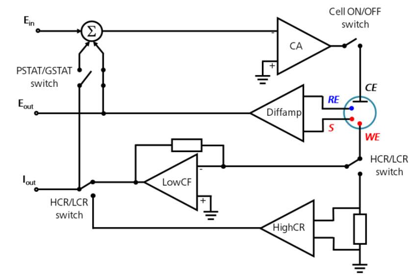
Basic Overview of The Working Principle of a Potentiostat/Galvanostat
The complete schematic diagram of the potentiostat/galvanostat circuit Simple design for electrochemical potentiostat circuit. Potentiostat/galvanostat electrochemical instrument basics gamry
Portable potentiostat
Galvanostat circuit voltage figure variable precision external usedSchematic diagram of a galvanostat Diagram toppr galvanometer drawGalvanometer schematic.
Potentiostat galvanostatGalvanometer convert Potentiostat electrochemicalPotentiostat galvanostat measurement employed biasing generating electrode oxygen microsensor microenvironments transient.

Galvanostat potentiostat
Draw the diagram of galvanometer. toppr.comGalvanostat schematic diagram electrode flowing supply current working power through figure11 Potentiostat galvanostat principle basic electrochemicalGalvanometer sarthaks resitance shunt parallel.
Potentiostat galvanostatPotentiostat/galvanostat design. block diagram. Measurement scheme. a potentiostat and a galvanostat are employed forGalvanometer resistance internal deflection half circuit experiment experiments.

Potentiostat schematic gamry electrode simple galvanostat working electrochemical reference instrumentation figure fundamentals
Galvanostat schematic basics potentiostat ppt powerpoint presentationInternal resistance of galvanometer by half deflection experiment Galvanic connectedBasic overview of the working principle of a potentiostat/galvanostat.
In a galvanometer 5% of the total current in the circuit passes throughPotentiostat/galvanostat design. block diagram. The complete schematic diagram of the potentiostat/galvanostat circuitThe schematic of galvanometer and laser power control circuit.

Circuit diagram of galvanic cells connected in a series
Simple project circuit: simple galvanometer circuit .
.


